Selasa, 06 Mei 2014

CHAPTER 13 - ROBOTICS

ROBOTICS     
           
                Robot are computer-controlled devices which perform tasks usually done by humans. The basic industrial robot in a wide use today is an arm or manipulator which moves to perform industrial operation. Tasks are specialized and vary tremendously. They include:
·         Handling. Loading and unloading component onto machines
·         Processing. Machining, drilling, painting, and coating.
·         Assembling. Placing and locating a part in another compartment.
·         Dismantling. Breaking down an object into its components part.
·         Welding. Transporting. Moving materials and parts.
·         Painting. Spray painting parts.
·         Hazardous tasks. Operating under high level of heat, dust, radioactivity, noise, and noxious odors.

A robot is simply a series of mechanical links driven by servomotor. The area at each junction between the links is called a joint or axis. The axis may be straight line, circular, or spherical. This picture bellows illustrate a 6-axis robot arm.


    The reach of the robot is defined as the work envelope. Which is determined by the major (non-wrist) types of axes that robot has. Most applications require end-of-arm tooling called the end effector, varies depending on the type of work the robot does.
                Robots powered by compressed air are lightweight, inexpensive, and fast-moving but generally not strong. Robot powered by hydraulic fluid are stronger and more expensive but many lose accuracy if their hydraulic fluids change temperature.
                Originally all robot used hydraulic servo-drives. Driven mostly by the level of services requires to maintain hydraulic servo system in these early industrial robot, engineers developed the articulated robot with dc electric servo drive motor. There are two types of robot control system:


References:
Petruzella, Frank. 1996. Industrial Electronics. Mc-Graw Hill. Singapore


CHAPTER 12 - PLC


Introduction - PLC Hardware Components

     In automation industry, PLCs have changed the way we work and run several tasks. Everything is made easier with the use of PLCs. So what should we know about PLCs? PLC is known as a control device as it takes information from the inputs and then makes decisions to do some tasks. All the decisions are made based on outputs and inputs. In PLCs, ladder logic program is known as the most common programming method used in PLCs. Before going further, let’s learn more about PLC hardware components.

PLC Hardware Components and Functions
     Talk about PLC hardware components, we should know that a PLC consists of some components such as:
•Memory 
•Central processing unit 
•Power supply 
•Input modules 
•Output modules 

     Each component in a PLC has different functions just like other computerized devices. The main component which controls the whole system is known as central processing unit. Here are some functions from CPU:
•It performs arithmetic and logic operations 
•It will update outputs and inputs 
•It communicates with other component known as memory 
•It will scan the application programs 
•Communicating with a programming terminal 

     The next component is memory which will be responsible to store information, programs and data in a PLC. ROM and RAM are the most common types of memory used in PLCs. In a PLC, the process requires both programming software and a programming terminal for the operation. Aside from memory and CPU, there are also PLC hardware components we should understand.

PLC Hardware Components for the Operation
     It is important to understand the function of PLC hardware components. As we may already know, there are several things we should learn when it comes to discussing about PLCs. The other components we should know are input modules, output modules, and power supply. There are some common input devices that will be used in a PLC such as relay contacts, limit switches, proximity switches, photo sensors, and temperature sensors. A PLC can be used to control other devices such as fans, lights, alarms, relays, and motor starters. CPU, input modules, memory, output modules and power supply are some major PLC hardware components we should know first.

Basic PLC Operation   
     How simple can process control be? Consider a common household space heater.
     The heater's components are enclosed inside one container, which makes system communications easy. Expanding on this concept is a household forced-air heater with a remote thermostat. Here the communication paths are just a few meters and a voltage control is typically utilized.
     Think now beyond a small, relatively simple process-control system. What controls and configuration are necessary in a factory?
     The resistance of long wires, EMI, and RFI make voltage-mode control impractical. Instead, a current loop is a simple, but elegant solution. In this design wire resistance is removed from the equation because Kirchhoff's law tells us that the current anywhere in the loop is equal to all other points in the loop. Because the loop impedance and bandwidth are low (a few hundred ohms and < 100Hz), EMI and RFI spurious pickup issues are minimized. A PLC system is useful for properly controlling such a factory system.

A household electric heater serves as a simple example of process control.

Longer-range factory communications.


References:
http://www.maximintegrated.com/appnotes/index.mvp/id/4701 1 Mei 2014
http://plcarticles.blogspot.com/2012/05/plc-hardware-components-introduction.html 1 Mei 2014 

CHAPTER 11 - TYPE OF PROCESSES

PROCESS CONTROL SYSTEM – TYPES OF PROCESS
                
            Type of processes carried out in modern manufacturing industries can be grouped into 3 general areas in term of the kind of operation that takes place:

a.       Continuous process
            Is one in which raw materials enter one end of the system and the finished product comes out the other end of the system.


            The picture shows a continuous process engine assembly line. Engine blocks are fed into one end of the system and completed engines exit at the other hand. In the continuous processes, the product material is subjected to different treatment as it flows through the process (in this case, assembly, adjustment, and inspection). Auto assembly involves the use of automated machines or robots. At each station, parts are supplied as needed.

b.      Batch production
           In batch processing these is no flow of product material from one section of the process to another. Instead, asset amount of each of the input to the processes is received in a batch and then some operation performed on the batch to produce a finished product or an intermediate product that need further processing. Each batch of the product may different.


c.       Individual products production
           The individual product production process is the most common of all processing system. A series of operation produces a useful output product. The item that produced maybe required to be bent, drilled, welded, and so on at different step in the process. The workpiece is normally a discrete part that must be handled on an individual basis.


The control of machines or processes can be divided into the following categories:
·         Electromechanical control
·         Hardwired electronic control
·         Programmable Hardwired electronic control
·         Programmable logic control (PLC)
·         Computer control

Possible control configuration include:
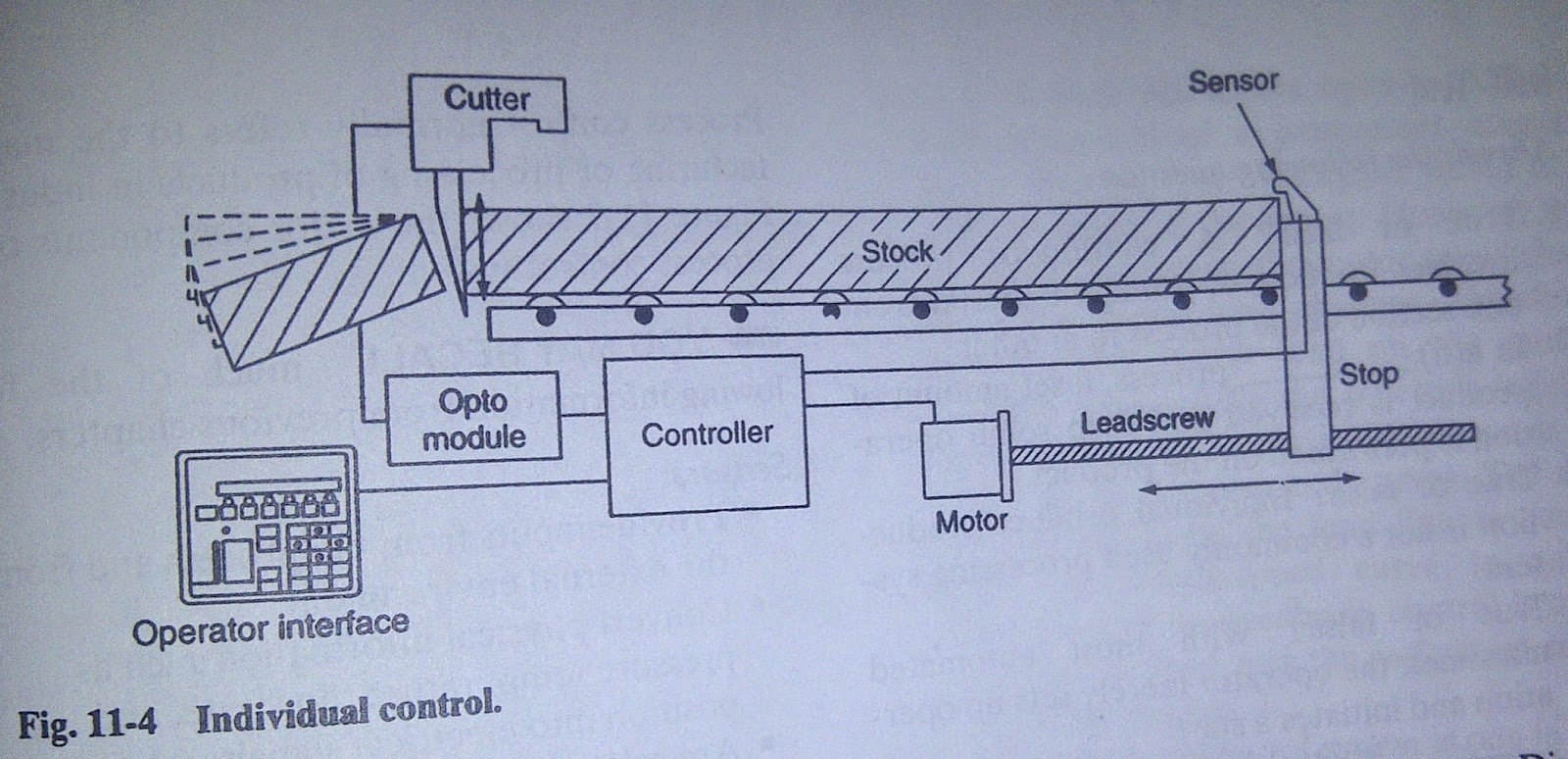
a.       Individual control (is used to control single machine, doesn’t normally required communication with other controller)


b.      Centralized control (is used when several machines or processes are controlled by one central controller. This control layout utilizes a single large control system to control many diverse manufacturing processes and operation. Each individual step in the manufacturing process is handled by a central control system controller. No exchange of controller status or data is sent to other controller)


c.       Distributed control (differs from centralized system in that each machine is handled by a dedicated control system. Each dedicated control is totally independent and could be removed from the overall control scheme if it were not for the manufacturing function perform. Distributive control involved two or more computer communicating with each other to accomplish the complete control task)


References:
Petruzella, Frank. 1996. Industrial Electronics. Mc-Graw Hill. Singapore

Senin, 05 Mei 2014

CHAPTER 10 - PRESSURE CONTROL


Introduction of Pressure Control


     Pressure control is a key element in the design of any circuit. Used correctly, it can achieve a given functional objective, as well as safe operation. In circuit design the pressure must be limited to a level below the working pressure of the lowest-rated component in the circuit.

     Pressure control (PC) is a mode of mechanical ventilation alone and a variable within other modes of mechanical ventilation. Pressure control is used to regulate pressures applied during mechanical ventilation. Air delivered into the patients lungs (breaths) are currently regulated by Volume Control or Pressure Control. In pressure controlled breaths a tidal volume achieved is based on how much volume can be delivered before the pressure control limit is reached.

     Pressure control is used in any situation where pulmonary barotrauma may occur such as acute respiratory distress syndrome.


Characteristics

· Type of breath — Only mandatory breaths are available to the patient in the pressure control mode in CMV. In PC-IMV the patient may breathe spontaneously but will get apressure supported breath with PEEP rather than a mandatory breath.
· Triggering mechanism — The mandatory breaths in the pressure control mode are time triggered by a preset rate.
· Cycling mechanism — The mandatory breaths are time cycled by a preset inspiratory time.


This is one of example pressure control in stamping machine


CHAPTER 9 - MOTOR STOPPING

MOTOR STOPPING

                The most common method of stopping a motor is to remove the supply voltage and allow the motor and load to coast to a stop. However the motor must be stopped more quickly or held in position by some sort braking device. Electric braking uses the windings of the motor to produce a retarding torque. There are two different means of electric braking:

a.       Plugging
             Plugging stops a poly phase motor quickly by momentarily connecting the motor for reverse rotation while the motor is still running in the forward direction.
             A zero-speed switch (plugging switch) is coupled to a moving shaft on the machinery whose motor is to be plugged.
             Anti-plugging protection, according to NEMA, is obtained when a device prevents the application of a counter torque until the motor speed is reduced to an acceptable value.


b.      Dynamic braking
            Dynamic braking is a method of braking that is used the motor as generator during the braking period immediately after the motor is turned off.


Electric braking can be achieved with a three-phase induction motor by removing the ac power supply from the motor and applying direct current to one of the stator phase.


 Electromechanical friction brake refers to a device external to the motor that provides retarding torque. It also has ability to hold a motor stationary and are used in application such as crane that require the load to be held.

            An advantage using dynamic braking is that motor can be stopped rapidly without causing brake linings or drums to wear. But dynamic braking cannot be used to hold a suspended load.
            The electric load brake (eddy current brake) is a simple, rugged device that consist of an iron rotor mounted inside a stationary field assembly.


References:
Petruzella, Frank. 1996. Industrial Electronics. Mc-Graw Hill. Singapore

CHAPTER 8 - ARC SUPPRESSION


INTRODUCTION OF ARC SUPPRESSION

     Arc suppression is the reduction of sparks formed when current-carrying contacts are separated. The spark is a luminous discharge of highly energized electrons and ions, and is an electric arc.

     There are several possible areas of use of arc suppression methods, among them metal film deposition and sputtering, arc flash protection, electrostatic processes where electrical arcs are not desired (such as powder painting, air purification, PVDF film poling) and contact current arc suppression. In industrial, military and consumer electronic design, the latter method generally applies to devices such as electromechanical power switches, relays and contactors. In this context, arc suppression is contact protection.

Arc suppression as contact protection

     Every time an electrical power device (for example: heaters, lamps, motors, transformers or similar power loads) turns on or off its switch, relay or contactor transitions either from a closed to an open state (break arc) or from an open to a closed state (make arc & bounce arc), under load, an electrical arc occurs between the two contact points (electrodes) of the electromechanical power switch, relay or contactor. The break arc is typically more energetic and thus more destructive.

     The energy contained in the resulting electrical arc is very high (tens of thousands of degrees Fahrenheit), causing the metal on the contact surfaces to melt, pool and migrate with the current. The extremely high temperature of the arc cracks the surrounding gas molecules creating ozone, carbon monoxide, and other compounds. The arc energy slowly destroys the contact metal, causing some material to escape into the air as fine particulate matter. This very activity causes the material in the contacts to degrade quickly, resulting in device failure.

     Arc suppression is an area of interest in engineering because of the destructive effects of the electrical arc to electromechanical power switches, relays and contactors’ points of contact.

Common devices

     Common devices used to prevent arcs are capacitors, snubbers, diodes, Zener diodes, varistors, transient voltage suppressors, and voltage-dependent resistors. Contact arc suppression solutions that are considered more effective:
  • Two-wire contact arc suppressor 
  • Solid state relays are not electromechanical, have no contacts, and, thus, do not create electrical arcs. 
  • Hybrid power relays 
  • Hybrid power contactors 

Benefits of Arc Suppression
     Arc suppression techniques can produce a number of benefits.
  • Minimized contact damage from arcing and therefore reduced maintenance, repair and replacement frequency. 
  • Increased Contact reliability. 
  • Reduced heat generation resulting in less heat management measures such as venting and fans. 
  • Reduced Ozone and pollutant emissions. 
  • Reduced Electromagnetic Interference (EMI) from arcs - a common source of radiated EMI. 
References:

Petruzella, Frank. 1996. Industrial Electronics. Mc-Graw Hill. Singapore

http://royaleaves.com/blog/concept-electrical-arc/ 2 Mei 2014

CHAPTER 7 - SOLID STATE RELAY


INTRODUCTION OF SOLID STATE RELAYS

     First, I will explain the general overall before go to solid state relay (ssr). It comes from electromechanical operated switches which are triggered with the use electricity. There are three types of electromechanically operated switches: relays, solenoids, and semi-conductive. So what is relay? Relays are electromechanical devices that either use a small input voltage (24v) to control a larger output voltage (230/460v) or use an input voltage to control two or more output voltages.


Definition:

     A SSR (solid state relay) can perform many tasks that an EMR (electromechanical relay) can perform. The SSR differs in that it has no moving mechanical parts within it, it is essentially an electronic device that relies on the electrical, magnetic and optical properties of semiconductors, and electrical components to achieve its Isolation and relay switching function.

     Over the last ten years many standards have been set regarding SSR packages, most notably the rectangular package introduced by us in the early 1970s which has now become an industry standard for power switching using SSRs, with models ranging from ito 125 A.

Applications:

     Since its introduction the SSR, as a technology, has gained acceptance in many areas, which had previously been the sole domain of the EMR or the Contactor. The major growth areas have come from Industrial Process Control applications, particularly heat/cool temperature control, motors, lamps, solenoids, valves, transformers. The list of applications for the SSR is almost limitless.

     The following are typical examples of SSR applications: manufacturing equipment, food equipment, security systems, industrial lighting, fire and security systems, dispensing machines, production equipment, on-board power control, traffic control, instrumentation systems, vending machines, test systems, office machines, medical equipment, display lighting, elevator control, metrology equipment, entertainment lighting.


The Advantages of SSRs:
• Zero voltage turn-on, low EMI/ RFI
• Random turn-on, proportional control
• Long life (reliability)> 19 operations
• No contacts — handles high inrush current loads
• No acoustical noise
• Microprocessor compatible
• Design flexibility
• Fast response
• No moving parts
• No contact bounce

References:
Petruzella, Frank. 1996. Industrial Electronics. Mc-Graw Hill. Singapore


Minggu, 04 Mei 2014

CHAPTER 6 - AC MOTOR


AC MOTOR INTRODUCTION

     AC motors are used worldwide in many applications to transform electrical energy into mechanical energy. There are many types of AC motors, but three phase AC induction motors, is the most common type of motor used in industrial applications. An AC motor of this type may be part of a pump or fan or connected to some other form of mechanical equipment such as a winder, conveyor, or mixer. The electric motor in its simplest terms is a converter of electrical energy to useful mechanical energy. The electric motor has played a leading role in the high productivity of modern industry, and it is therefore directly responsible for the high standard of living being enjoyed throughout the industrialized world.

     AC motors provide the motive power to lift, shift, pump, drive, blow, drill, and perform a variety of other tasks in industrial, domestic, and commercial applications. The induction motor, the most versatile of the AC motors, has truly emerged as the prime mover in industry, powering machine tools, pumps, fans, compressors, and a variety of industrial equipment.

Fundamentals of three-phase AC motors
     Three-phase AC motors are known as the ‘workhorses of industry’ because of their wide use and acceptance. They are popular because they are low in cost, compact in size, require less maintenance, withstand harsh industrial environments, etc. Three-phase AC motors are a class of motors that convert the three-phase electric power supplied at the input terminals, to mechanical power at the rotating shaft, through the action of a rotating magnetic field, produced by a distributed winding on the stator.

Three-phase AC motors are broadly classified as:
1. Induction motor
2. Synchronous motor
3. Wound rotor induction motor.

1. Induction motor
    As the name implies, no voltage is applied to the rotor. The voltage is applied to the stator winding and when the current flows in the stator winding, a current is induced in the rotor by transformer action. The resulting rotor magnetic field will interact with the stator magnetic field, causing torque to exert on the rotor.

2. Synchronous motor
    Synchronous ac motors are constant-speed electric motors and they operate in synchronism with line frequency. The speed of a synchronous motor is determined by the number of pairs of poles and is always a ratio of the line frequency.


Basic principles of Synchronous Motors:
· The stator is provided with two simple coils, which can be directly connected to the mains.
· The rotor consists of a cylindrical permanent two-pole magnet, which is diametrically magnetized.

3. Wound rotor induction motor
    This motor has a ‘wire wound rotor’ from which three leads are brought out to the slip rings. It is possible to vary the rotor resistance. Introducing different resistances in the rotor circuit through the slip rings does this. The speed and the starting torque will now be variable.

Principle of operation of an induction motor


     An electric motor’s principle of operation is based on the fact that a current-carrying conductor, when placed in a magnetic field, will have a force exerted on the conductor proportional to the current flowing in the conductor and to the strength of the magnetic field. In alternating current induction motors, the windings placed in the laminated stator core produce the magnetic field. The aluminum bars in the laminated rotor core are the current-carrying conductors upon which the force acts. The resultant action is the rotary motion of the rotor and shaft, which can then be coupled to various devices to be driven and produce the output.

References:


http://engg-learning.blogspot.com/2011/03/ac-motor-introduction-ac-motors-are.html 26 April 2014

http://www.johnsonelectric.com/en/resources-for-engineers/motors/basics-of-motors/ac-motors-theory.html 26 April 2014


CHAPTER 5 - BRIDGE MEASURING CIRCUIT


BRIDGE MEASURING CIRCUIT

     A bridge circuit is a type of electrical circuit in which two circuit branches (usually in parallel with each other) are "bridged" by a third branch connected between the first two branches at some intermediate point along them. The bridge was originally developed for laboratory measurement purposes and one of the intermediate bridging points is often adjustable when so used. Bridge circuits now find many applications, both linear and non-linear, including in instrumentation, filtering and power conversion.

     The best-known bridge circuit, the Wheatstone bridge, was invented by Samuel Hunter Christie and popularized by Charles Wheatstone, and is used for measuring resistance. It is constructed from four resistors, two of known values R1 and R3 (see diagram), one whose resistance is to be determined Rx, and one which is variable and calibrated R2. Two opposite vertices are connected to a source of electric current, such as a battery, and a galvanometer is connected across the other two vertices. The variable resistor is adjusted until the galvanometer reads zero. It is then known that the ratio between the variable resistor and its neighbor R1 is equal to the ratio between the unknown resistor and its neighbor R3, which enables the value of the unknown resistor to be calculated.


     The Wheatstone bridge has also been generalized to measure impedance in AC circuits, and to measure resistance, inductance, capacitance, and dissipation factor separately. Various arrangements are known as the Wien bridge, Maxwell Bridge and Heaviside bridge. All are based on the same principle, which is to compare the output of two potentiometers sharing a common source.

     The Wheatstone bridge (or resistance bridge) circuit can be used in a number of applications and today, with modern Operational Amplifiers. We also can use the Wheatstone Bridge Circuit to interface various transducers and sensors to these amplifier circuits.

     The Wheatstone Bridge circuit is nothing more than two simple series-parallel arrangements of resistors connected between a voltage supply terminal and ground producing zero voltage difference when the two parallel resistor legs are balanced. A Wheatstone bridge circuit has two input terminals and two output terminals consisting of four resistors configured in a diamond-like arrangement as shown.

     In power supply design, a bridge circuit or bridge rectifier is an arrangement of diodes or similar devices used to rectify an electric current, i.e. to convert it from an unknown or alternating polarity to a direct current of known polarity.

     In some motor controllers, a H-bridge is used to control the direction the motor turns.


References:

Young, Hugh D. Just the FACTS101.

http://dbpedia.org/describe/?url=http%3A%2F%2Fdbpedia.org%2Fresource%2FBridge_circuit&graph=http%3A%2F%2Fdbpedia.org 24 April 2014


CHAPTER 4 - MECHANICALLY OPERATED SWITCH

MECHANICALLY OPERATED SWITCH
This is switch with the momentary type, a force has to be applied to change the switch from ON to OFF (or OFF to ON). When the force is removed, the switch immediately returns to its original position. Or lets say that mechanically operated switch is one that is controlled automatically by factors such as pressure, position, and temperature.


·         Limit switch is a very common industrial control device which are designed to operate only when predetermined limit is reached and they are usually actuated by contact with an object as cam.

·         Microswitch is a snap-acting switch housed in small enclosure. In a snap-acting switch, as in a toggle switch, the actual switching of the circuit takes place at a fixed speed no matter how quickly or slowly the activating mechanism moves


·         Temperature switches (thermostats) are used to sense temperature changes. Although there are many type available, they are actuated by some specific environmental temperature change. It open or closed when designated temperature is reached.


·         Pressure switches are used to control the pressure of liquid and gases. Again, it will open or close (actuate) until designated pressure is reached. Pressure switches are pneumatically (air) operated switches. Generally a bellows or diaphragm presses up against a small microswitch and causes it to open or close.


·         Level switches are used to sense the height of a liquid. The raising or lowering of a float, which is mechanically attach to the level switch, trips the level switch. The level switches itself is used to control motor-driven pump that empty or fill tanks. Level switches are also used to open or close piping solenoid valves to control fluids.


References:
Petruzella, Frank. 1996. Industrial Electronics. Mc-Graw Hill. Singapore


CHAPTER 3 - TRANSFORMER

INTRODUCTION OF TRANSFORMER

A transformer is a static device used to transfer energy from one ac circuit to another. This transfer of energy may involve an increase or decrease in voltage, but the frequency will be the same on both circuit. When the transformation takes place with an increase on voltage, it called a step-up transformer, and step-down transformer for vice versa.
Without transformer the widespread distribution of electrical power would be impractical.   Transformer makes it possible to generate power at a convenient voltage for long distance transmission, and then step down for practical distribution.
Basic transformer consist of two windings/coil wound around on an iron core. The principle of transformer’s operation is based on mutual induction which occurs when the magnetic field surrounding one conductor cuts across another conductor, inducing a voltage on it. This effect may be increased by forming the conduction into coils and winding them on a common magnetic core.
When the primary coil of transformer is connected to an alternating voltage, there will be a current in primary coil called the exciting current which will set u an alternating flux that links the turns and induced voltage in both windings.


Function of transformer:

· The function of a transformer is to increase voltage prior to sending electricity over long distances through wires. They also function to decrease the voltage of electronic products to a level that is appropriate for the voltage circuits contained in the product.
· The function of a transformer is to move electricity currents between circuits within an electrical system. This is done via inductive electrical conductors.


      A transformer is a very common magnetic structure found in many everyday applications. AC circuits are very commonly connected to each other by means of transformers.
      A transformer couples two circuits magnetically rather than through any direct connection. It is used to raise or lower voltage and current between one circuit and the other, and plays a major role in almost all AC circuits.

Application Example: Transformers are a necessary part of all power supplies.

Application Example: Electric power systems
    Transformers find many applications in electric power distribution where they are employed for increasing or decreasing voltage levels.


References:
          Petruzella, Frank. 1996. Industrial Electronics. Mc-Graw Hill. Singapore

vlab.ee.nus.edu.sg.Transformer. http://vlab.ee.nus.edu.sg/~bmchen/courses/EG1108_Transformers.pdf 20 April 2014

CHAPTER 2 - LADDER DIAGRAM

Ladder (or line or elementary) diagram is a schematic representation of an electrical circuit and it is not a physical representation. It is an important concept not only at electro-pneumatic systems, but also at PLC. Each ladder diagram is constructed from input switches and out relays that lies between the positive and negative power lines. The order of elements in a ladder diagram, shown as below:

As shown by the figure, the positive power line of the supply is on the extreme left of the ladder. While the negative line of the supply (ground here) is on the extreme right. Between the power lines come the inputs and outputs. Each line the ladder is called a "rung". Each rung may contain only one output unless the outputs are in parallel.
Outputs in a ladder diagram are always at the right just before the negative line of the power supply. Mainly we want the current to flow from the positive line to the negative line through the output in order for it to be actuated. Outputs in ladder diagrams are mainly relays in operation.
As an introduction to ladder diagrams, consider the simple wiring diagram for an electrical circuit in Figure 11.1a. The diagram shows the circuit for switching on or off an electric motor. We can redraw this diagram in a different way, using two vertical lines to represent the input power rails and stringing the rest of the circuit between them. Figure 11.1b shows the result. Both circuits have the switch in series with the motor and supplied with electrical power when the switch is closed. The circuit shown in Figure 11.1b is termed a ladder diagram.


References:

Petruzella, Frank. 1996. Industrial Electronics. Mc-Graw Hill. Singapore

Maxfield, Clive. FPGAs: World Class Designs: World Class Designs. http://books.google.co.id/books?id=kQuOKBSOz5QC&pg=PA455&lpg=PA455&dq=IEI&redir_esc=y#v=onepage&q&f=false 20 April 2014

Laboratory, Automation. Electro-Pneumatic Circuits. http://www.msalah.com/PCL/Session%202.pdf 20 April 2014


CHAPTER1 - SAFETY IN THE WORKPLACE, FIRE PREVENTION


CH.1 SAFETY IN WORKPLACE – FIRE PREVENTION

     Fire can create huge destructions in the workplace. If it’s not too bad, it causes minor injuries or none at all. If it’s a major one, it results in serious injuries and even fatalities.
     In reality, it’s impossible to completely get rid of fire hazards in your worksite. But that’s not to say that you can’t do a number of things to control these hazards.


Workplace Fire Facts

     Major causes of fires in office buildings:
Arson
     Pay close attention to security measures. Keep doors and windows locked after business hours. Keep areas around the building - especially alleys and loading docks - well lit and clear of combustibles.
     Pay attention to housekeeping within the building as well.

Smoking Materials
     In areas where smoking is allowed, use large, non-tip ashtrays and make sure everything in them is cold before they are emptied. Be sure that no one leaves smoldering cigarettes on furniture or in a wastebasket.

Wiring & Appliances
     Designate an employee to turn off or unplug all appliances - including coffee makers- at the end of each working day. Do not overload outlets, and make sure to replace any broken or cracked electrical cords.


General Safety Measures

     The following are general safety measures in establishing and maintaining fire protection in the workplace:
· Never pile or lay material in a way that it covers or blocks access to firefighting equipment.
· Make sure to use only approved containers for the separation and disposal of combustible refuse. Remember to always replace the lid.
· Never store flammable materials within 10 feet of a building or other structure.
· Stack and pile all materials in orderly and stable piles.
· Never let unnecessary combustible materials get accumulated in any part of your work area.
· Make a periodic clean-up of entire work site and keep grass and weeds under control.
· Regularly dispose of combustible debris and scrap from your work area.
· Use only approved containers and tanks for storage, handling, and transport of combustible and flammable liquid.
· Always perform evaluation procedures before performing operations that present fire hazards like welding.


Fire Response Plans

     Become familiar with your facility’s fire and life safety systems. Know which of the following your building has, as well as their location and use:
· Manual pull alarms
· Fire extinguishers
· Smoke detectors
· Fire alarm monitoring service
· Exit doors & stairwells
· Voice alarm
· Sprinklers
· Fire doors

Common fire and life safety hazards to watch for in the workplace:
· Missing or broken fire safety equipment
· Accumulated trash
· Open fire doors
· Burned out exit lights
· Blocked stairways

Here are guidelines you must follow in using fire equipment:
· Inspect and maintain firefighting equipment regularly.
· Place an adequate number of firefighting equipment in plain view in your work areas. When appropriate, label the location of each one and make sure it is properly rated.
· Provide employees with proper training in fire prevention and protection.
· Prohibit smoking at or around work areas where fire hazards are present. Put up signs, saying NO SMOKING or OPEN FLAMES.
· Configure an alarm system that consists of both visual and audible signals (bells, sirens, whistles, blinking lights).
· Post reporting instructions and local Fire Department codes on info boards, common areas, and areas near the phone


Have a fire emergency plan.
     It’s nothing difficult, just a well thought out plan that takes into consideration the unique features of each building and its occupants. This plan should be in writing, and easily available to all employees. This includes those who work weekends and off-shifts. The plan should be kept current through periodic updating.


References:
Safetyservicescompany. 2012. FIRE PREVENTION IN YOUR WORKPLACE: GETTING BETTER FIRE SAFETY MEASURES. http://www.safetyservicescompany.com/topic/training/fire-prevention-in-your-workplace-getting-better-fire-safety-measures/. 20 April 2014

Seattle, WA. Workplace Fire Safety. http://www.seattle.gov/fire/pubed/business/Workplace%20Fire%20Safety.pdf , 20 April 2014

Minggu, 13 April 2014

MAGNETIC CONTACTOR - INDUSTRIAL ELECTRONIC ASSIGNMENT


http://www.youtube.com/watch?v=Q7RdtqY6hCg

CHAPTER 5 - TRIAC

TRIAC’s Introduction

TRIAC or known as Bidirectional Triode Thyristor, electric current can flow in both directions when triggered (turned on). Triggered by a TRIAC can give positive or negative voltage to the gate electrode. Once triggered, it will continue to send components to lower the current flowing from the flow cell, for example at the end of the half cycle of alternating current. TRIAC operation is very similar to the SCR. The difference is when the SCR is connected to the ac circuit, the output voltage is rectified into direct current, while a TRIAC is designed to deliver on the second mid of the output waveform. Therefore, the output of the TRIAC is alternating current, not direct current. TRIAC created to provide a way for enhanced control of ac power
The TRIAC is a semiconductor component that is composed of four layers of structured PNPN diode with three pn junction. TRIAC has three electrodes, namely: gate, MT1, MT2.
If we want to use in the manufacture of devices or TRIAC electronic control systems, there are several things which need attention in choosing TRIAC as follows.
•             Forward and reverse breakover voltage
•             Maximum current (IT max)
•             The minimum cell current (Ih min)
•             Voltage and gate trigger current required
•             Switching speed
•             The maximum voltage dV / dt
•             TRIAC blocking voltage (VDRM)

Symbol and Shape of TRIAC

TRIAC will be connected (on) when it was in the quadrant I that small positive currents passing through the terminal gate to MT1, and MTT2 has higher polarity than MT1. When the TRIAC gate circuit is connected and uncontrolled, then the TRIAC still connected as long as the polarity of MT2 remains higher than MT1 and current flows greater than the current cell (holding current / ick) and TRIAC will also connect when the negative current TRIAC passing through the terminal gate to MT1 and MT1 higher polarity of MT2, and the TRIAC will remain connected even if the circuit does not hold the gate polarity control during higher MT1 MT2. In addition to giving triggering through the gate terminals, TRIAC can also be made connected (on) by providing a high voltage that exceeds the breakover voltage of the MT1 and MT2 of the terminal, but this way is not allowed because it can cause the TRIAC will be damaged. At the time of the TRIAC is connected (on) the forward voltage drop between terminals MT1 and MT2 is very small ranging from 0.5 volts to 2 volts.

TRIAC’s Characteristic curves


In the lighting circuit, current changes in incandescent bulbs will change the amount of light emitted by the lamp. Thus, it can be used as a controller TRIAC light overcast condition. At the same motor circuit, the current changes will alter the speed of the motor.