Selasa, 06 Mei 2014

CHAPTER 13 - ROBOTICS

ROBOTICS     
           
                Robot are computer-controlled devices which perform tasks usually done by humans. The basic industrial robot in a wide use today is an arm or manipulator which moves to perform industrial operation. Tasks are specialized and vary tremendously. They include:
·         Handling. Loading and unloading component onto machines
·         Processing. Machining, drilling, painting, and coating.
·         Assembling. Placing and locating a part in another compartment.
·         Dismantling. Breaking down an object into its components part.
·         Welding. Transporting. Moving materials and parts.
·         Painting. Spray painting parts.
·         Hazardous tasks. Operating under high level of heat, dust, radioactivity, noise, and noxious odors.

A robot is simply a series of mechanical links driven by servomotor. The area at each junction between the links is called a joint or axis. The axis may be straight line, circular, or spherical. This picture bellows illustrate a 6-axis robot arm.


    The reach of the robot is defined as the work envelope. Which is determined by the major (non-wrist) types of axes that robot has. Most applications require end-of-arm tooling called the end effector, varies depending on the type of work the robot does.
                Robots powered by compressed air are lightweight, inexpensive, and fast-moving but generally not strong. Robot powered by hydraulic fluid are stronger and more expensive but many lose accuracy if their hydraulic fluids change temperature.
                Originally all robot used hydraulic servo-drives. Driven mostly by the level of services requires to maintain hydraulic servo system in these early industrial robot, engineers developed the articulated robot with dc electric servo drive motor. There are two types of robot control system:


References:
Petruzella, Frank. 1996. Industrial Electronics. Mc-Graw Hill. Singapore


CHAPTER 12 - PLC


Introduction - PLC Hardware Components

     In automation industry, PLCs have changed the way we work and run several tasks. Everything is made easier with the use of PLCs. So what should we know about PLCs? PLC is known as a control device as it takes information from the inputs and then makes decisions to do some tasks. All the decisions are made based on outputs and inputs. In PLCs, ladder logic program is known as the most common programming method used in PLCs. Before going further, let’s learn more about PLC hardware components.

PLC Hardware Components and Functions
     Talk about PLC hardware components, we should know that a PLC consists of some components such as:
•Memory 
•Central processing unit 
•Power supply 
•Input modules 
•Output modules 

     Each component in a PLC has different functions just like other computerized devices. The main component which controls the whole system is known as central processing unit. Here are some functions from CPU:
•It performs arithmetic and logic operations 
•It will update outputs and inputs 
•It communicates with other component known as memory 
•It will scan the application programs 
•Communicating with a programming terminal 

     The next component is memory which will be responsible to store information, programs and data in a PLC. ROM and RAM are the most common types of memory used in PLCs. In a PLC, the process requires both programming software and a programming terminal for the operation. Aside from memory and CPU, there are also PLC hardware components we should understand.

PLC Hardware Components for the Operation
     It is important to understand the function of PLC hardware components. As we may already know, there are several things we should learn when it comes to discussing about PLCs. The other components we should know are input modules, output modules, and power supply. There are some common input devices that will be used in a PLC such as relay contacts, limit switches, proximity switches, photo sensors, and temperature sensors. A PLC can be used to control other devices such as fans, lights, alarms, relays, and motor starters. CPU, input modules, memory, output modules and power supply are some major PLC hardware components we should know first.

Basic PLC Operation   
     How simple can process control be? Consider a common household space heater.
     The heater's components are enclosed inside one container, which makes system communications easy. Expanding on this concept is a household forced-air heater with a remote thermostat. Here the communication paths are just a few meters and a voltage control is typically utilized.
     Think now beyond a small, relatively simple process-control system. What controls and configuration are necessary in a factory?
     The resistance of long wires, EMI, and RFI make voltage-mode control impractical. Instead, a current loop is a simple, but elegant solution. In this design wire resistance is removed from the equation because Kirchhoff's law tells us that the current anywhere in the loop is equal to all other points in the loop. Because the loop impedance and bandwidth are low (a few hundred ohms and < 100Hz), EMI and RFI spurious pickup issues are minimized. A PLC system is useful for properly controlling such a factory system.

A household electric heater serves as a simple example of process control.

Longer-range factory communications.


References:
http://www.maximintegrated.com/appnotes/index.mvp/id/4701 1 Mei 2014
http://plcarticles.blogspot.com/2012/05/plc-hardware-components-introduction.html 1 Mei 2014 

CHAPTER 11 - TYPE OF PROCESSES

PROCESS CONTROL SYSTEM – TYPES OF PROCESS
                
            Type of processes carried out in modern manufacturing industries can be grouped into 3 general areas in term of the kind of operation that takes place:

a.       Continuous process
            Is one in which raw materials enter one end of the system and the finished product comes out the other end of the system.


            The picture shows a continuous process engine assembly line. Engine blocks are fed into one end of the system and completed engines exit at the other hand. In the continuous processes, the product material is subjected to different treatment as it flows through the process (in this case, assembly, adjustment, and inspection). Auto assembly involves the use of automated machines or robots. At each station, parts are supplied as needed.

b.      Batch production
           In batch processing these is no flow of product material from one section of the process to another. Instead, asset amount of each of the input to the processes is received in a batch and then some operation performed on the batch to produce a finished product or an intermediate product that need further processing. Each batch of the product may different.


c.       Individual products production
           The individual product production process is the most common of all processing system. A series of operation produces a useful output product. The item that produced maybe required to be bent, drilled, welded, and so on at different step in the process. The workpiece is normally a discrete part that must be handled on an individual basis.


The control of machines or processes can be divided into the following categories:
·         Electromechanical control
·         Hardwired electronic control
·         Programmable Hardwired electronic control
·         Programmable logic control (PLC)
·         Computer control

Possible control configuration include:
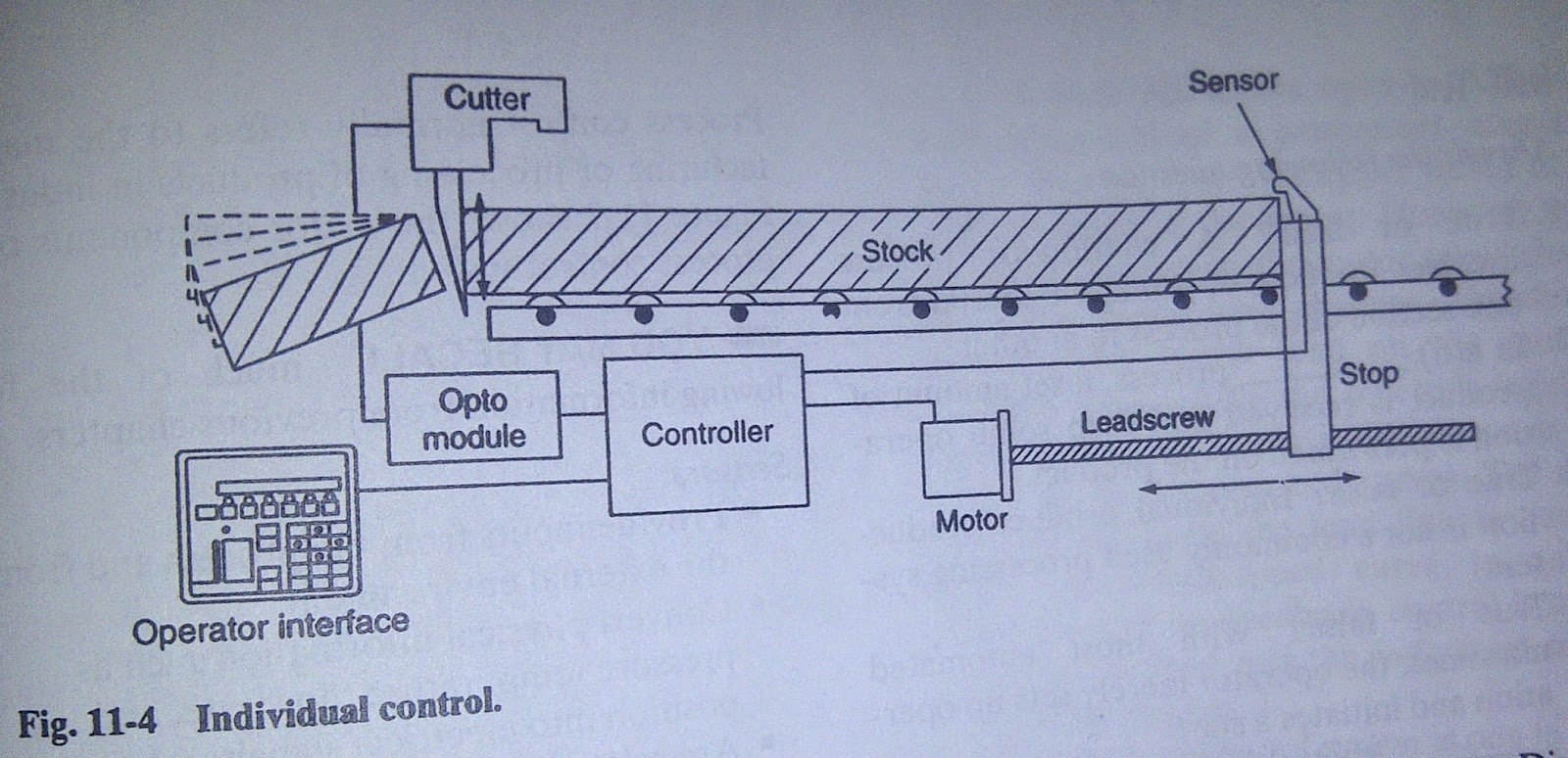
a.       Individual control (is used to control single machine, doesn’t normally required communication with other controller)


b.      Centralized control (is used when several machines or processes are controlled by one central controller. This control layout utilizes a single large control system to control many diverse manufacturing processes and operation. Each individual step in the manufacturing process is handled by a central control system controller. No exchange of controller status or data is sent to other controller)


c.       Distributed control (differs from centralized system in that each machine is handled by a dedicated control system. Each dedicated control is totally independent and could be removed from the overall control scheme if it were not for the manufacturing function perform. Distributive control involved two or more computer communicating with each other to accomplish the complete control task)


References:
Petruzella, Frank. 1996. Industrial Electronics. Mc-Graw Hill. Singapore

Senin, 05 Mei 2014

CHAPTER 10 - PRESSURE CONTROL


Introduction of Pressure Control


     Pressure control is a key element in the design of any circuit. Used correctly, it can achieve a given functional objective, as well as safe operation. In circuit design the pressure must be limited to a level below the working pressure of the lowest-rated component in the circuit.

     Pressure control (PC) is a mode of mechanical ventilation alone and a variable within other modes of mechanical ventilation. Pressure control is used to regulate pressures applied during mechanical ventilation. Air delivered into the patients lungs (breaths) are currently regulated by Volume Control or Pressure Control. In pressure controlled breaths a tidal volume achieved is based on how much volume can be delivered before the pressure control limit is reached.

     Pressure control is used in any situation where pulmonary barotrauma may occur such as acute respiratory distress syndrome.


Characteristics

· Type of breath — Only mandatory breaths are available to the patient in the pressure control mode in CMV. In PC-IMV the patient may breathe spontaneously but will get apressure supported breath with PEEP rather than a mandatory breath.
· Triggering mechanism — The mandatory breaths in the pressure control mode are time triggered by a preset rate.
· Cycling mechanism — The mandatory breaths are time cycled by a preset inspiratory time.


This is one of example pressure control in stamping machine


CHAPTER 9 - MOTOR STOPPING

MOTOR STOPPING

                The most common method of stopping a motor is to remove the supply voltage and allow the motor and load to coast to a stop. However the motor must be stopped more quickly or held in position by some sort braking device. Electric braking uses the windings of the motor to produce a retarding torque. There are two different means of electric braking:

a.       Plugging
             Plugging stops a poly phase motor quickly by momentarily connecting the motor for reverse rotation while the motor is still running in the forward direction.
             A zero-speed switch (plugging switch) is coupled to a moving shaft on the machinery whose motor is to be plugged.
             Anti-plugging protection, according to NEMA, is obtained when a device prevents the application of a counter torque until the motor speed is reduced to an acceptable value.


b.      Dynamic braking
            Dynamic braking is a method of braking that is used the motor as generator during the braking period immediately after the motor is turned off.


Electric braking can be achieved with a three-phase induction motor by removing the ac power supply from the motor and applying direct current to one of the stator phase.


 Electromechanical friction brake refers to a device external to the motor that provides retarding torque. It also has ability to hold a motor stationary and are used in application such as crane that require the load to be held.

            An advantage using dynamic braking is that motor can be stopped rapidly without causing brake linings or drums to wear. But dynamic braking cannot be used to hold a suspended load.
            The electric load brake (eddy current brake) is a simple, rugged device that consist of an iron rotor mounted inside a stationary field assembly.


References:
Petruzella, Frank. 1996. Industrial Electronics. Mc-Graw Hill. Singapore

CHAPTER 8 - ARC SUPPRESSION


INTRODUCTION OF ARC SUPPRESSION

     Arc suppression is the reduction of sparks formed when current-carrying contacts are separated. The spark is a luminous discharge of highly energized electrons and ions, and is an electric arc.

     There are several possible areas of use of arc suppression methods, among them metal film deposition and sputtering, arc flash protection, electrostatic processes where electrical arcs are not desired (such as powder painting, air purification, PVDF film poling) and contact current arc suppression. In industrial, military and consumer electronic design, the latter method generally applies to devices such as electromechanical power switches, relays and contactors. In this context, arc suppression is contact protection.

Arc suppression as contact protection

     Every time an electrical power device (for example: heaters, lamps, motors, transformers or similar power loads) turns on or off its switch, relay or contactor transitions either from a closed to an open state (break arc) or from an open to a closed state (make arc & bounce arc), under load, an electrical arc occurs between the two contact points (electrodes) of the electromechanical power switch, relay or contactor. The break arc is typically more energetic and thus more destructive.

     The energy contained in the resulting electrical arc is very high (tens of thousands of degrees Fahrenheit), causing the metal on the contact surfaces to melt, pool and migrate with the current. The extremely high temperature of the arc cracks the surrounding gas molecules creating ozone, carbon monoxide, and other compounds. The arc energy slowly destroys the contact metal, causing some material to escape into the air as fine particulate matter. This very activity causes the material in the contacts to degrade quickly, resulting in device failure.

     Arc suppression is an area of interest in engineering because of the destructive effects of the electrical arc to electromechanical power switches, relays and contactors’ points of contact.

Common devices

     Common devices used to prevent arcs are capacitors, snubbers, diodes, Zener diodes, varistors, transient voltage suppressors, and voltage-dependent resistors. Contact arc suppression solutions that are considered more effective:
  • Two-wire contact arc suppressor 
  • Solid state relays are not electromechanical, have no contacts, and, thus, do not create electrical arcs. 
  • Hybrid power relays 
  • Hybrid power contactors 

Benefits of Arc Suppression
     Arc suppression techniques can produce a number of benefits.
  • Minimized contact damage from arcing and therefore reduced maintenance, repair and replacement frequency. 
  • Increased Contact reliability. 
  • Reduced heat generation resulting in less heat management measures such as venting and fans. 
  • Reduced Ozone and pollutant emissions. 
  • Reduced Electromagnetic Interference (EMI) from arcs - a common source of radiated EMI. 
References:

Petruzella, Frank. 1996. Industrial Electronics. Mc-Graw Hill. Singapore

http://royaleaves.com/blog/concept-electrical-arc/ 2 Mei 2014

CHAPTER 7 - SOLID STATE RELAY


INTRODUCTION OF SOLID STATE RELAYS

     First, I will explain the general overall before go to solid state relay (ssr). It comes from electromechanical operated switches which are triggered with the use electricity. There are three types of electromechanically operated switches: relays, solenoids, and semi-conductive. So what is relay? Relays are electromechanical devices that either use a small input voltage (24v) to control a larger output voltage (230/460v) or use an input voltage to control two or more output voltages.


Definition:

     A SSR (solid state relay) can perform many tasks that an EMR (electromechanical relay) can perform. The SSR differs in that it has no moving mechanical parts within it, it is essentially an electronic device that relies on the electrical, magnetic and optical properties of semiconductors, and electrical components to achieve its Isolation and relay switching function.

     Over the last ten years many standards have been set regarding SSR packages, most notably the rectangular package introduced by us in the early 1970s which has now become an industry standard for power switching using SSRs, with models ranging from ito 125 A.

Applications:

     Since its introduction the SSR, as a technology, has gained acceptance in many areas, which had previously been the sole domain of the EMR or the Contactor. The major growth areas have come from Industrial Process Control applications, particularly heat/cool temperature control, motors, lamps, solenoids, valves, transformers. The list of applications for the SSR is almost limitless.

     The following are typical examples of SSR applications: manufacturing equipment, food equipment, security systems, industrial lighting, fire and security systems, dispensing machines, production equipment, on-board power control, traffic control, instrumentation systems, vending machines, test systems, office machines, medical equipment, display lighting, elevator control, metrology equipment, entertainment lighting.


The Advantages of SSRs:
• Zero voltage turn-on, low EMI/ RFI
• Random turn-on, proportional control
• Long life (reliability)> 19 operations
• No contacts — handles high inrush current loads
• No acoustical noise
• Microprocessor compatible
• Design flexibility
• Fast response
• No moving parts
• No contact bounce

References:
Petruzella, Frank. 1996. Industrial Electronics. Mc-Graw Hill. Singapore